


Note: This appears as Chapter 4 in Missile Defense 2020: Next Steps for Defending the Homeland.
Ground-based Interceptor Development
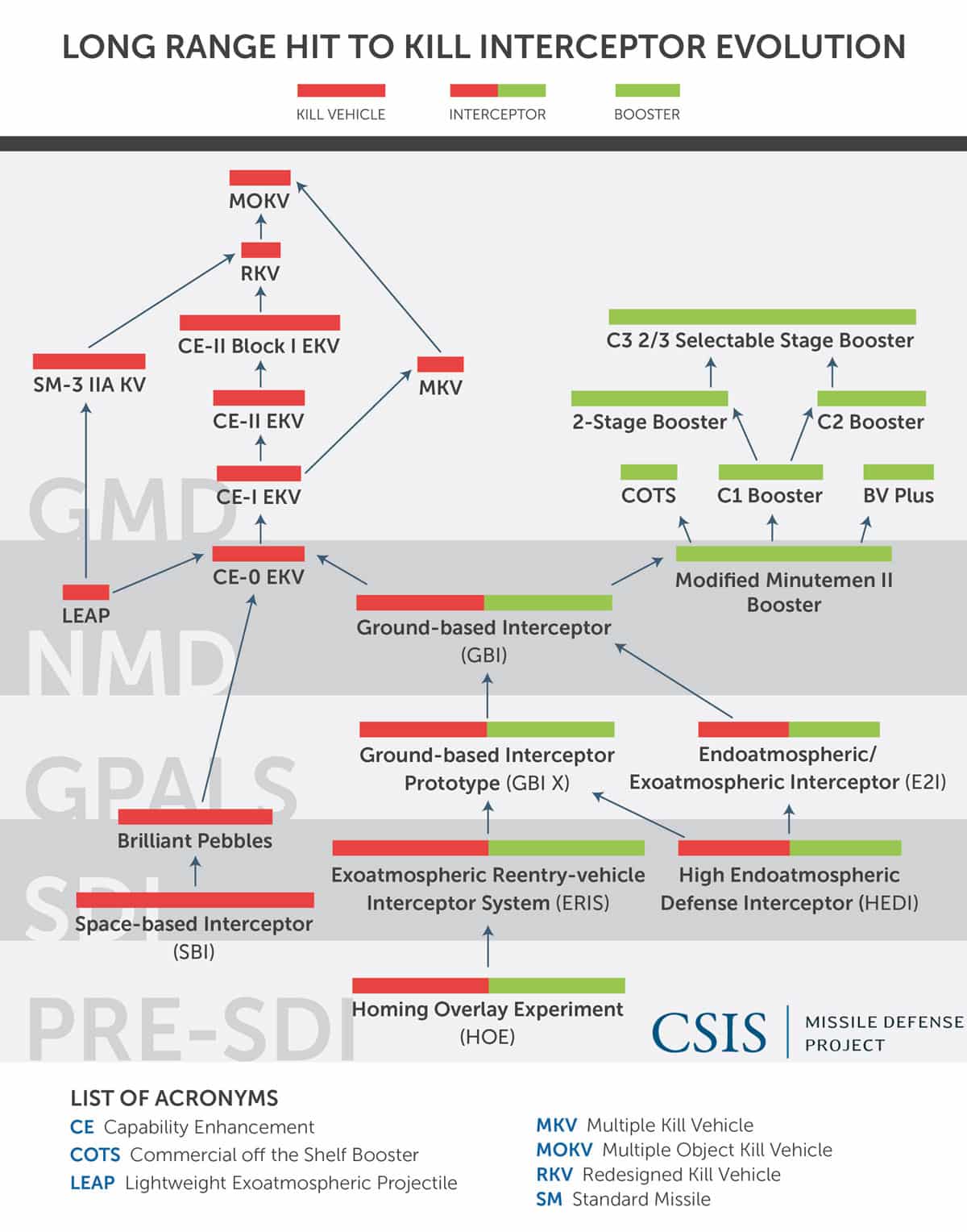
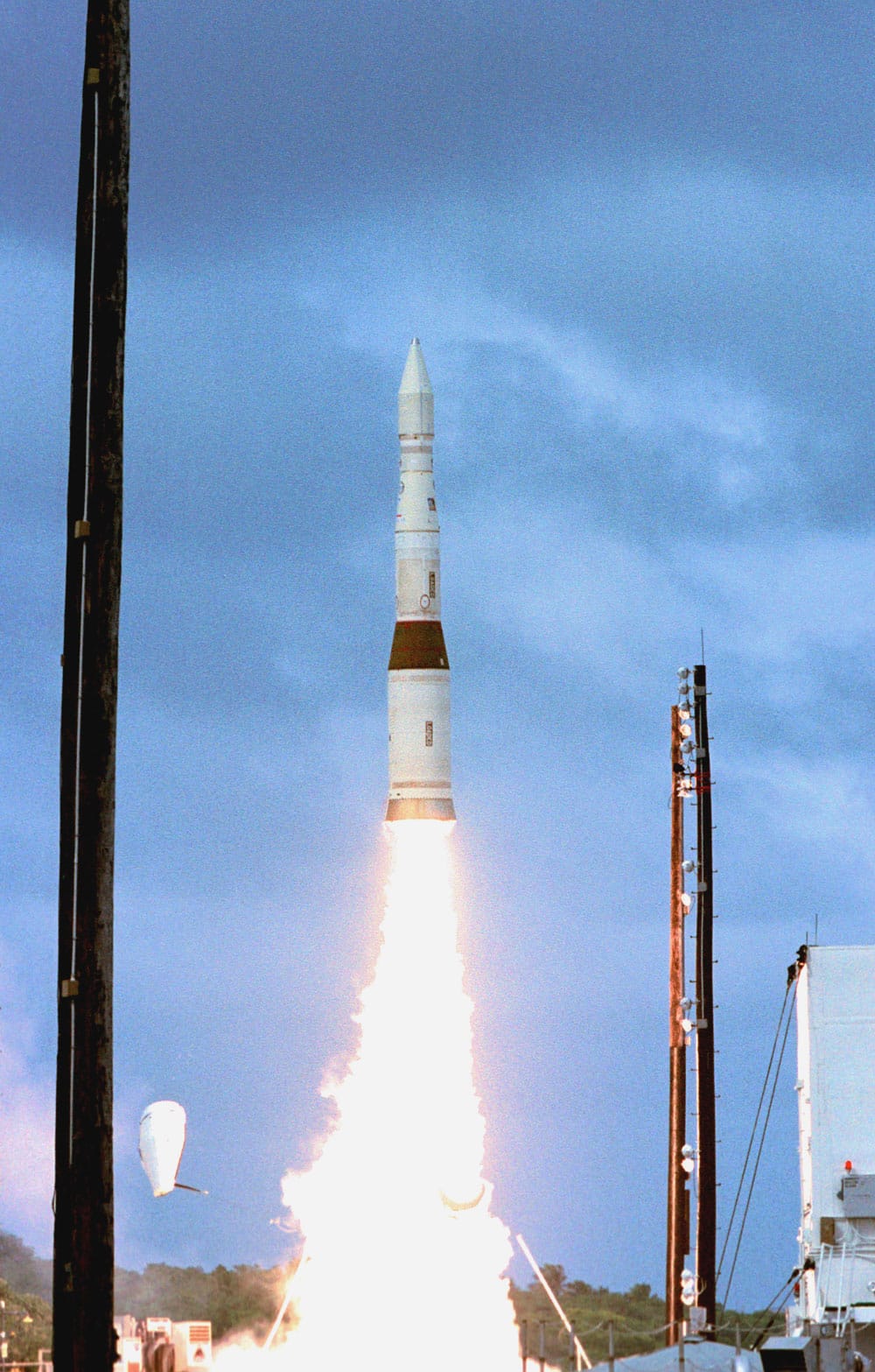
Perhaps the most recognizable component of homeland missile defense is the Ground-based Interceptor (GBI) itself, which represents the product of a long line of hit-to-kill interceptors dating back to the 1980s (Figure 4.1). Many of the same basic concepts and technologies that brought the HOE to collide with a dummy warhead in 1984 are still employed in the kill vehicles aboard today’s interceptors. The GBI testing regime since 1999 has likewise helped to identify numerous technical issues that have further refined the system. These advancements in hit-to-kill technology have been buoyed by the creation of an integrated network of sensors and command and control infrastructure. As of 2016, there are 36 GBIs deployed, the bulk at Fort Greely, Alaska, and a handful at Vandenberg AFB in California.1 Some 44 GBIs are expected to be deployed by the end of 2017.2
GBI VARIANTS
Because the 2002 decision for deployment essentially fielded an advanced prototype, every early kill vehicle was unique, handmade in about 130,000 steps. The gradual progress of modernization and increases in capacity have resulted in a further diversity in the actual interceptors deployed. Five main variants of GBIs are currently fielded, in the process of being deployed, or in development. These vary based on their combinations of the kill vehicle and booster (Table 4.1).
The Redesigned Kill Vehicle (RKV) will decrease both the diversity and complexity across the fleet, aiding in the production and improving reliability. Even after RKV is fully deployed in 2027, however, the planned fleet of 44 will still include nine comparatively older GBIs equipped with CE-II Block 1 kill vehicles.
| Model | Kill Vehicle | Booster | 2017 Fleet |
| GBI Block 1 | CE-I | C1 | 20 |
| GBI Block 2A | CE-II | C1 | 16 |
| GBI Block 2B | CE-II Block 1 | C2 | 8 |
| GBI Block 3A | RKV (in development) | C1 | – |
| GBI Block 3B | RVK (in development) | C3 | – |
Exoatmospheric Kill Vehicles (EKVs)
Four main variants of the EKV have been tested since GMD began intercept tests in 1999: CE-0, CE-I, CE-II, and CE-II Block 1. The CE-0 name signifies a prototype only used in testing and never deployed. The CE-I is the operationally deployed version of the original prototype. In 2008, MDA began replacing obsolete components on some of the CE-I EKVs, along with other upgrades, which resulted in the CE-II EKV. The CE-II, first tested in January 2010, underwent a reconfiguration based on the results of its intercept and flight testing. The newest variant tested, the CE-II Block 1, features an upgraded set of alternate divert thrusters and is currently being applied to the nine additional GBIs being deployed to Fort Greely.
Booster Vehicles
Two variants of booster are present in today’s GBI fleet, the C1 and C2, both of which have three stages. The third stage gives the current GBIs extended range, but limits their ability to conduct intercepts later in a target missile’s flight, as the third stage must first burn before the EKV can be deployed.
The C1 booster is nearing obsolescence due to lack of available of spare parts. C2 boosters feature an upgraded avionics package to increase reliability, as well as obsolescence upgrades. There are, however, no current plans to upgrade the existing C1 fleet to C2, and the C1 is expected to remain in service into the 2024–2025 time frame.
TESTING AND DEPLOYMENT HISTORY
One of the most important parts of the GMD development effort has been the regime of GBI flight and intercept testing. Intercept tests typically involve the launch of an IRBM or ICBM representative target, followed by the launch of a single GBI to engage it. Other flight tests involve only the launch of an interceptor to prove out kill vehicles or other sensor systems. MDA also carries out various ground and sensor-only tests to exercise GMD’s support systems.
Since 1997, there have been 31 GBI flight and intercept tests.3 When examined together, these tests reveal several basic insights:
- Flight and intercept testing has been among the best ways to discover system flaws not otherwise revealed through ground testing and to validate the fixes meant to resolve them.
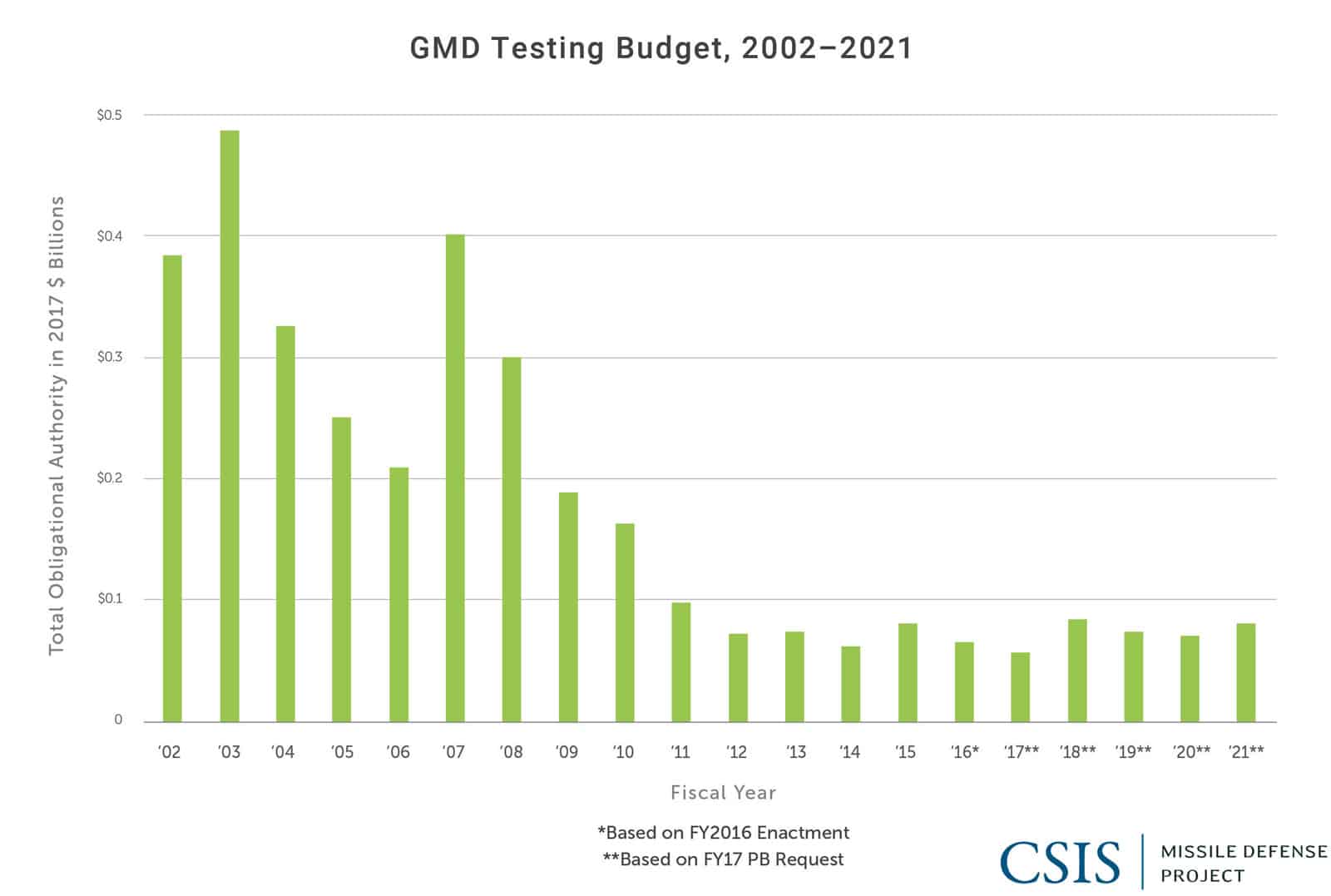
- GMD’s flight and intercept testing cadence has been irregular, in part due to the need to investigate several test failures and also a decline in the overall GMD testing budget (Figure 4.3).
- The GMD testing regime has not revealed fundamental flaws in the technological foundations behind hit-to-kill missile defense. The vast majority of intercept failures have been the result of inconsistencies in interceptor manufacturing as well “test anomalies,” such as malfunctions in test-only equipment, such as with surrogate boosters not originally designed to carry a kill vehicle and with the silos themselves.
- The historical progression of GMD tests reflects significant growth in the number of operational components, particularly the integration of sensors (Table 4.2).
- MDA has made efforts to improve the operational realism of its intercept tests, including with the employment of countermeasures, but it is difficult to assess whether these improvements have made the tests as realistic as they could be.
The following sections describe the history and lessons learned from over 19 years of GBI tests.
Early Testing
The first tests of the EKV were in 1997 and 1998 as part of the National Missile Defense (NMD) program, followed by an intercept test in October 1999.4 In that test, a CE-0 prototype carried on a modified Minuteman II ICBM successfully collided with a dummy warhead deployed by another modified Minuteman.5
The target missile reportedly also deployed a decoy balloon, demonstrating a nascent ability for the EKV to discriminate between lethal and nonlethal objects.6 The test did not involve the use of an external radar. Instead the dummy warhead and decoys were equipped with C-band transponders to signal their locations, approximating tracking information that would have been provided by a ground-based radar.7
A follow-on intercept test in January 2000 failed, resulting from blockage within the EKV’s coolant system that interfered with the performance of the kill vehicle’s seeker. Another test failure occurred in July the same year, a result of a failure in the booster’s data bus that prevented the kill vehicle from separating. This failure was somewhat anomalous, as the modified Minuteman surrogate booster was not originally designed to carry the EKV and would not have been part of any deployed missile defense system.8 It was nevertheless part of the basis on which President Clinton deferred a deployment decision in late 2000.
These two failed tests were then followed by four confirmed intercepts in a row from July 2001 to October 2002. In each of these intercepts, the target deployed penetration aids to test the system’s discrimination capabilities. According to MDA, the October 2002 intercept test contained five objects in the threat cloud, three of which were decoys.9
The final test using the CE-0 kill vehicle failed to intercept due to flaws with the Laser Firing Unit, later described as a “very simple, mechanical type of issue.”10
Concurrent with these early tests of the EKV was the development of a dedicated booster to carry the EKV. This element of the GBI development went through several “fits and starts,” with several potential boosters being considered.11
In 2002, the Director of the Operational Test and Evaluation (DOT&E) office identified two main weaknesses of the GBI program and its testing regimen: the lack of a deployable boost vehicle, and the lack of realistic testing. Specifically, the DOT&E report noted that all intercept tests to that point had “similar fly-out and engagement procedures.” Further intercept testing was suspended in 2002 until MDA had a dedicated and flight-tested booster.12
Limited Defensive Operations
In accordance with President George W. Bush’s NSPD-23, MDA began preparing GMD for deployment and initial operations. In January 2004, the Orbital booster achieved a successful simulated intercept, and became MDA’s choice for initial deployment.13 This paved the way for the completion of a new test bed at Vandenberg AFB and the resumption of intercept testing. Initial planning called for six GBIs at Fort Greely and four at Vandenberg AFB by 2004, with another 10 to be in place at Fort Greely by 2005.14
Two GBI launch failures in late 2004 and early 2005 (IFT-13c, IFT-14) halted further testing, pending the findings of an independent review team. The December 2004 failure resulted from a booster “software design error in an automated diagnostic check run prior to launch.”15 Another in February 2005 failed to even launch due to a rusted silo arm that failed to fully retract. A defect in the test bed silo caused the malfunction, not an operational silo designed to house the interceptors long-term. MDA characterized both as “built in test anomalies” that did not necessarily reflect failures of the interceptors or the overall GMD system.16 The 2005 DOT&E report cited “quality, workmanship, and inadequate ground testing . . . as contributing factors.”17
In response to recommendations of the review panel, MDA conducted a series of nonintercept tests throughout 2005. These included six ground tests, two target-only flight tests to gauge ground radar performance, and one interceptor-only demonstration flight test (FT-1).18 FT-1 was the first flight test of a GBI tipped with the CE-I kill vehicle. By the end of FY 2005, nine operational GBIs had been emplaced at Fort Greely.19 Between 2006 and 2008, MDA adopted an annual testing cadence that saw three successful intercept tests of the CE-I EKV and Orbital booster (FTG-02, FTG-03a, FTG-05).
| Flight / Intercept Test | Date | KV | Sensor Systems Employed | Notes | ||||||
| UEWR | SPY-1 | SBX | TPY-2 | STSS | OPIR | Intercept? | ||||
| IFT-1 | 17-Jan-97 | CE-0 | n/a | Data link malfunction-launch aborted | ||||||
| IFT-1a | 7-Jul-97 | CE-0 | n/a | Flight test only | ||||||
| IFT-2 | 15-Jan-98 | CE-0 | n/a | Flight test only | ||||||
| IFT-3 | 2-Oct-99 | CE-0 | Y | Single Decoy | ||||||
| IFT-4 | 19-Jan-00 | CE-0 | N | EKV foreign object coolant blockage | ||||||
| IFT-5 | 8-Jul-00 | CE-0 | N | Failed booster separation | ||||||
| BV-1 | 28-Apr-01 | n/a | Vehicle did not launch; Boeing Booster Vehicle | |||||||
| IFT-6 | 14-Jul-01 | CE-0 | Y | |||||||
| BV-2 | 31-Aug-01 | n/a | Boeing Booster Vehicle | |||||||
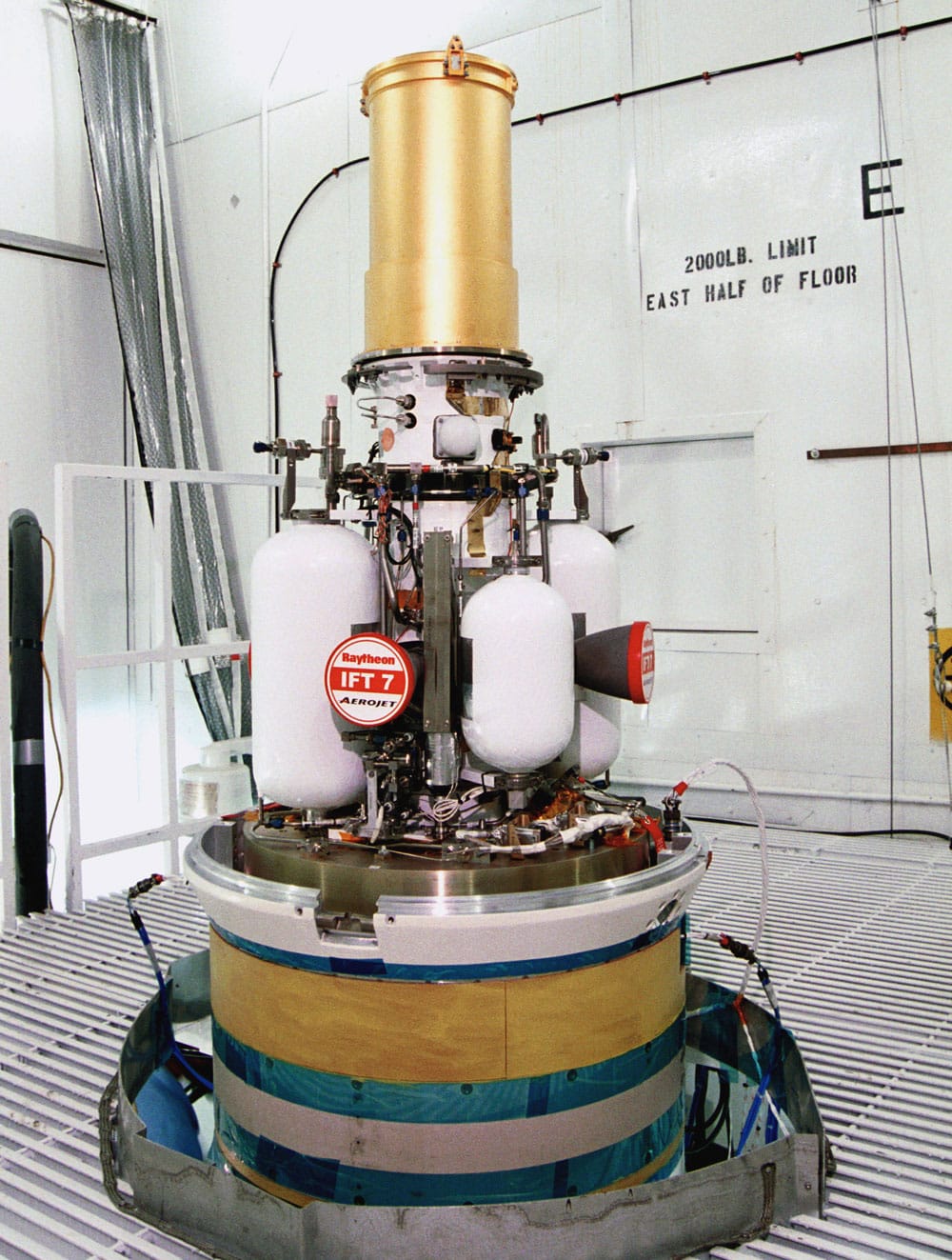
| IFT-7 | 3-Dec-01 | CE-0 | Y | |||||||
| BV-3 | 13-Dec-01 | n/a | Flight test failure; Boeing Booster Vehicle | |||||||
| IFT-8 | 15-Mar-02 | CE-0 | Y | |||||||
| IFT-920 | 14-Oct-02 | CE-0 | • | Y | ||||||
| IFT-10 | 11-Dec-02 | CE-0 | • | N | EKV failed to separate | |||||
| BV-6 | 16-Aug-03 | n/a | Successful booster test; Orbital Booster Vehicle | |||||||
| BV-5a | 9-Jan-04 | n/a | Successful booster test; Lockheed Martin BV+Vehicle | |||||||
| IFT-13b21 | 24-Jan-04 | • | n/a | Successful test of Orbital Booster Vehicle | ||||||
| IFT-13c | 15-Dec-04 | CE-0+ | • | N | Failed to launch, software design error | |||||
| IFT-14 | 14-Feb-05 | CE-0+ | N | Failed to launch | ||||||
| FT-01 | 13-Dec-05 | CE-I | n/a | Nonintercept test | ||||||
| FTG-0222 | 1-Sep-06 | CE-1 | • | • | • | • | Y | |||
| FTG-0323 | 25-May-07 | CE-I | • | • | • | • | n/a | No test (target failure) | ||
| FTG-03a | 28-Sep-07 | CE-I | • | • | • | • | • | Y | ||
| FTG-0524 | 5-Dec-08 | CE-I | • | • | • | • | • | Y | ||
| FTG-06 | 31-Jan-10 | CE-II | • | • | • | • | N | Missing DACS lock wire, SBX malfunction | ||
| BVT-01 | 6-Jun-10 | • | • | n/a | 2-stage booster test only; Orbital Booster Vehicle | |||||
| FTG-06a | 15-Dec-10 | CE-II | • | • | • | • | • | N | Track gate anomaly | |
| GM CTV-01 | 26-Jan-13 | CE-II | n/a | Nonintercept test | ||||||
| FTG-0725 | 5-Jul-13 | CE-I | • | • | • | • | N | Battery power loss | ||
| FTG-06b26 | 22-Jun-14 | CE-II | • | • | • | Y | ||||
| GM CTV-02+ | 28-Jan-16 | CE-II Block 1 | • | • | • | n/a | Nonintercept test |
Note: This table includes GBI flight and intercept tests. MDA conducts numerous other kinds of GMD tests, including sensor-only tests and ground tests. While important, these tests are not listed here.
In December 2008, FTG-05 was the first intercept test using track data from multiple BMDS sensors.27 The interceptor experienced an unidentified malfunction but nonetheless achieved a successful intercept.28 By the end of 2008, a total of 24 CE-I GBIs had been deployed, 21 at Fort Greely, with another three at Vandenberg, as well as the completion of the necessary infrastructure, including silos and power needs, to support 30 interceptors between the two sites.29
CE-II Reconfiguration and the Track Gate Anomaly
Near the end of 2008, MDA began upgrading obsolete elements of the kill vehicles, primarily the processor and software, as well as making “minor” improvements for producibility.30 The sum of these alterations resulted in the CE-II EKV. MDA attempted an intercept test with a CE-II EKV in January 2010, but it failed. Test diagnostics identified the cause of the failure as a “missing lockwire in the DACS” and “undesirable performance of the Sea-based X-band Radar.”31
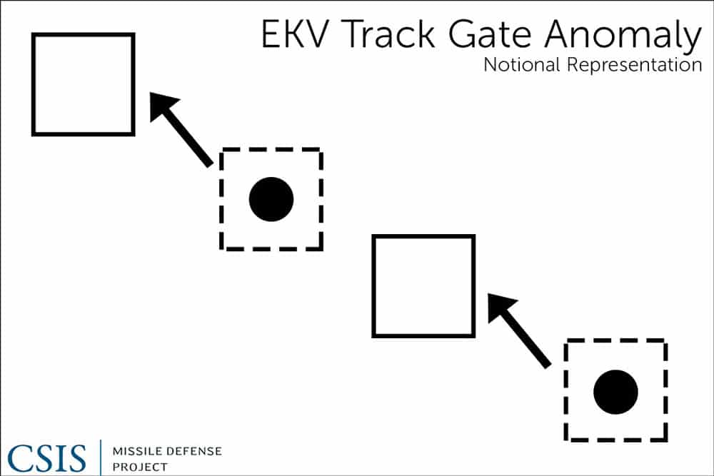
The CE-II experienced a second failed intercept in December 2010. This failure was a result of a “track gate anomaly” within the kill vehicle. This anomaly had been a “long historical issue,” first noticed in IFT-06 in 2001.32 Initially thought to be caused by electromagnetic interference, the problem was ultimately determined to be the result of high frequency vibrations within the kill vehicle. Specifically, the vibrations affected the EKV’s Inertial Measurement Unit (IMU), which caused the tracks to “shift,” resulting in an inaccurate target picture of the incoming warhead (Figure 4.5). Although the anomaly had been known to exist since 2001, the issue had not affected EKV performance until FTG-06, when it corresponded with the inclusion of a more sensitive IMU.
Return to Intercept
Once isolated, MDA corrected the track gate anomaly by updating IMU firmware and adding an isolation “cradle” around the IMU to better shield it from vibration. MDA then conducted a successful interceptor-only EKV characterization flight test, CTV-01, in January 2013. This flight test was then followed by the CE-II’s first successful intercept, FTG-06b, in June 2014. Beyond validating the fixes to the IMU firmware, FTG-06b included a target missile that approached ICBM speeds. The EKV also demonstrated the ability to correctly discriminate and intercept a reentry vehicle in the presence of operationally realistic countermeasures.33
In January 2016, MDA conducted a nonintercept flight test (CTV-02+) to prove out an upgraded system of divert thrusters, which allow the EKV to maneuver in space. These thrusters were designed to further reduce the effects of vibration of the IMU, the root cause of failed intercept tests in 2010.34 This upgraded version of the CE-II, designated the CE-II Block 1, also features a redesigned fuel tank for greater producibility and reliability. Although interception was not the goal of the test, a target IRBM was launched, allowing the sensor network to gather data for future discrimination techniques.
Utility of Testing
GBI testing since 1999 has uncovered several critical shortcomings of the GMD system. In most cases, however, these issues have been indicative of the kind of issues that are to be expected during an engineering cycle (Table 4.3). Indeed, with the exception of the track gate anomaly, no identified malfunction has ever affected the results of more than one test. As MDA Director Vice Admiral James Syring noted in 2014:
So these were the eight failures that we account for . . . the top five are on the CE-0 venture, [and] again the direction [was] to rapidly field a prototype, but it was a test bed at the time with a design cycle, I would even say half complete. So that, to me, would not be unexpected . . . nothing unexpected in a prototype for a test bed. More issues . . . that you work out in the test phase of a program.35
These details help put the long history of NMD/GMD testing record into context. What makes GMD relatively unique is not the presence of failures, but rather that the system is operational even while design flaws are worked out and enhancements made. None of the issues that have arisen over 19 years of GBI testing challenge the basic technological soundness of hit-to-kill technology or of the GMD system overall.
| Test | Date | Cause |
| IFT-1 | 17-Jan-97 | Data link malfunction, launch aborted |
| IFT-4 | 19-Jan-00 | EKV foreign object coolant blockage |
| IFT-5 | 8-Jul-00 | Failed booster separation, booster avionics package failure |
| IFT-10 | 11-Dec-02 | EKV failed to separate, failure in laser firing unit |
| IFT-13c | 15-Dec-04 | Failed to launch, software design error |
| IFT-14 | 14-Feb-05 | Failed to launch, silo support arm failure |
| FTG-06 | 31-Jan-10 | Missing DACS lock wire, SBX malfunction |
| FTG-06a | 15-Dec-10 | Track gate anomaly |
| FTG-07 | 5-Jul-13 | Battery power loss |
CURRENT INTERCEPTOR LIMITATIONS
One major limitation on the effectiveness of the current GBI fleet is the lack of regular in-flight updates to the EKV. As MDA has noted, ground systems currently “don’t communicate very often today with the kill vehicle.”36 Today’s GMD in-flight communications are inferior in this respect to more recently developed regional systems such as the Standard Missile-3.
The current three-stage booster configuration also limits flexibility to perform shorter-range shots at incoming missiles later in flight, since all three stages of the booster must burn out before the kill vehicle can be deployed. A shorter-range shot later in the missile’s trajectory may be necessary if an initial GBI salvo fails to intercept, or if there is insufficient warning time. A fleet composed of only three-stage boosters compresses the battlespace that operators have to engage a set of incoming targets and reduces the ability to intercept “leakers” if initial interceptors fail.
Notwithstanding MDA’s chartered mission to defeat missiles in all phases of flight, the ability to intercept missiles in the boost phase is lacking from not only the current BMDS configuration but also near-term planning within MDA. Such capabilities would of course require means of intercept other than GBIs. The 2010 budget request included language in its cancellation of the Multiple Kill Vehicle (MKV) stating that “we decided to focus resources instead on technologies that are designed to defeat advanced countermeasures of launched missiles in their ascent phase.”37 That 2010 request did not, however, contain any new spending on ascent-phase programs. The only ascent-phase intercept program of record at the time, the Airborne Laser (ABL), saw its spending reduced that year to $187 million, down from $401 million the previous fiscal year.38 The program was terminated shortly thereafter, though recent years have seen some movement to begin funding a low-power laser demonstrator aboard a UAV platform that could have ascent-phase applications.39
PLANNED IMPROVEMENTS
Several programs are under way to increase the reliability and flexibility of the GBIs, as well as reduce costs. These include both second- and third-generation kill vehicle programs (RKV, MOKV) as well as a selectable-stage booster.
Redesigned Kill Vehicle (RKV)
Currently in full-scale development, the RKV is being designed to improve on and eventually replace the existing fleet of prototype CE-I and CE-II EKVs. While not a radical departure from the current EKV, the RKV will feature a streamlined design, making it more modular and more producible. The new design will also reduce the number of failure points, increasing its reliability and warfighter confidence. The streamlined design is expected to have significantly fewer parts with easier accessibility, simplifying maintenance. MDA has said that the RKV will “increase performance to address the evolving threat, improve in-flight communications to better utilize off-board sensor data, and enhance Combatant Commanders’ situational awareness via hit/kill assessment messages.”40
This effort to improve on EKV is both welcome and long overdue. The 2002 deployment decision required the fielding of a kill vehicle that was little more than an advanced prototype and had been created under the strictures of the ABM Treaty. Vice Admiral Syring has described RKV as the first effort “since the 1990s, to improve dramatically upon the EKV, using a modular open architecture based on common interfaces and standards. This effort is designed to improve reliability, availability, maintainability, testability, producibility, and unit manufacturing cost.”41 Various advances have been made over the past 15 years that have been applied to other parts of the BMDS, but similar qualitative improvements have thus far been mostly lacking for GBIs. Even RKV is not a major improvement on EKV in terms of basic concept or design.
Some RKV elements have already undergone some flight testing, such as the upgraded divert thrusters tested in January 2016 as part of the CE-II Block 1 EKV.42 Vice Admiral Syring has also stated that the RKV will feature “on demand communication . . . [which] will allow us to update the kill vehicle much more frequently,” noting that this capability is already available for the Aegis system and Standard Missiles.43 The previous Common Kill Vehicle (CKV) effort prepared the way for applying preexisting or common features, such as ondemand communications, that already exist. RKV is also expected to have the ability to communicate with other kill vehicles to reduce the chance that two or more kill vehicles will engage the same object within the threat cloud. Should this effort be successful, GBIs could come to have reliability similar to the Standard Missile and other regional missile defenses.
From 2015 to 2016, Congress appropriated $373.6 million to develop RKV, with an additional budget request of $274.15 million for RKV in 2017. In February 2015, Vice Admiral Syring estimated the total cost of RKV development at $658 million.44
MDA expects to begin RKV flight testing in the 2018 time frame. Planned intercept tests include a two-stage GBI with an RKV engaging an IRBM target in summer of 2019, and a two- or threestage selectable GBI with an RKV against an ICBM-class target in winter 2019–2020. Initial production deliveries are expected around 2020.
Multi-Object Kill Vehicle (MOKV)
The MOKV represents a third-generation kill vehicle, building on EKV, RKV, and other current BMDS elements, such as SM-3. It, too, is intended to improve the capacity, reliability, communications, and discrimination of homeland missile defense. MOKV is tailored to the goal of “volume kill,” meaning hitting a number of targets within the threat cloud created by a given threat missile launch. Rather than equipping a single GBI with the single kill vehicle, each booster would carry several smaller kill vehicles, each with some degree of independent guidance. The MOKV could reduce some of the expectation for ground-based sensors to adequately discriminate warheads from debris and decoys, allowing a single GBI to engage multiple objects within a single threat cluster, or perhaps take more than one shot at a single object.
During congressional testimony in 2009, General James Cartwright, the vice chair of the Joint Chiefs of Staff, spoke to the shot doctrine issue, noting that the previously planned deployment of 10 GBIs to Europe would only have been able to intercept a maximum of five missiles, “assuming a shot doctrine of two interceptors against each threat missile.”45 The reference to two per target is a sort of minimum for reliability, but the statement presupposes the optimistic assumption of perfect discrimination of the threat cloud, and the GBI shot doctrine is almost certainly higher given the current reliability of today’s system. A more complete description might have described a shot doctrine of at least two (perhaps more) kill vehicles per object within the missile threat cloud that might be a warhead. MDA has described MOKV as “allow[ing] us to go not just to the most lethal object but to the next one and the next one and the next one. And if you can do that, you can kill everything on the scene and you’ll be sure that you got it.”46 Given that these kill vehicles would be smaller and lighter than today’s family of EKVs, an MOKV cluster might look more like a cluster of SM-3 IIA-sized kill vehicles, or even smaller.
A previous “volume kill” program, the Multiple Kill Vehicle (MKV) program, was canceled by the Obama administration in 2009. The MKV completed a hover test on December 2, 2009. According to MDA, the MKV’s “propulsion system demonstrated maneuverability while tracking a target” and “transmitted video and flight telemetry to the ground.”47
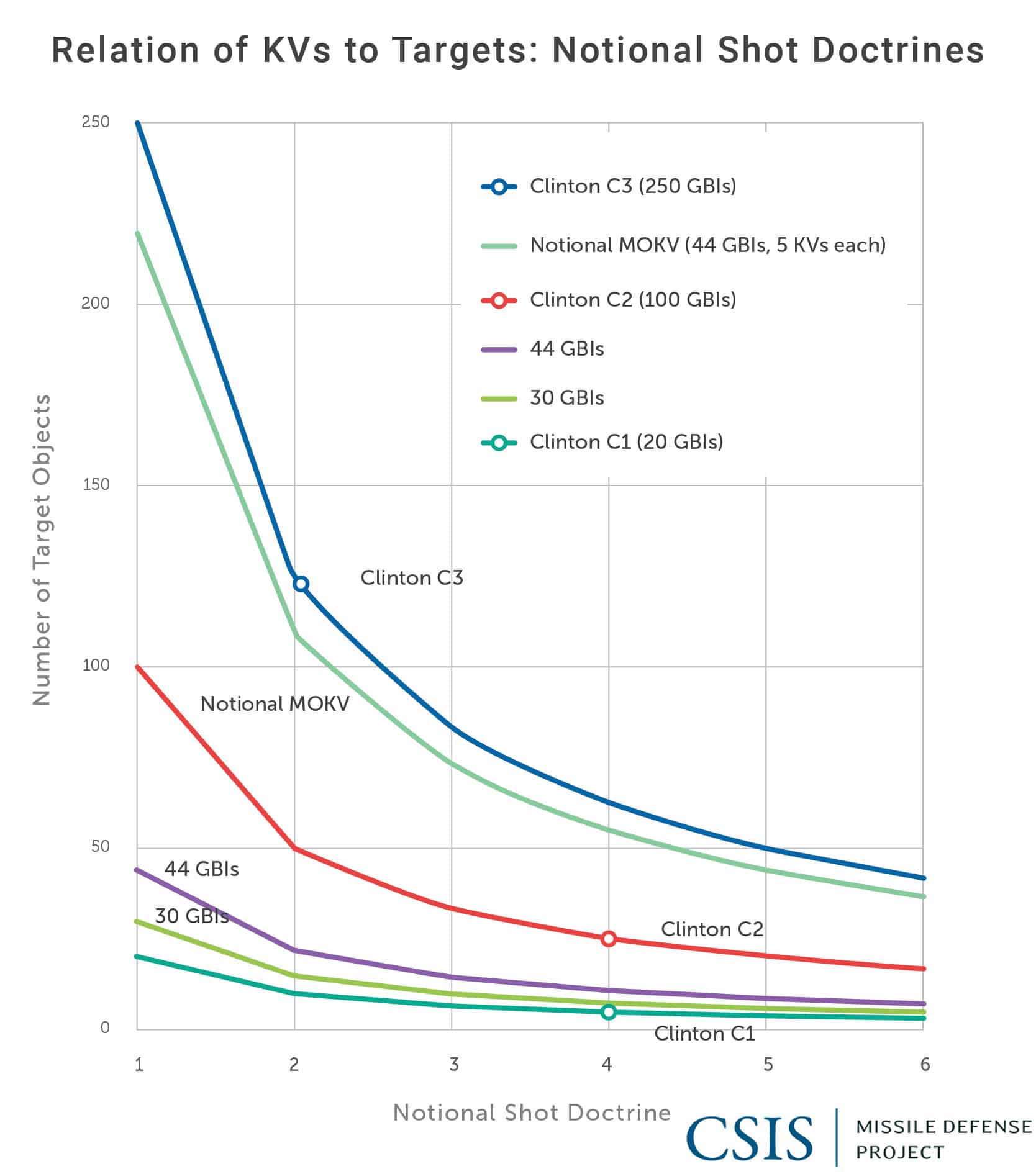
Putting more than one interceptor on a given GBI round has significant potential to improve shot doctrine and therefore increase effective inventory capacity. Figure 4.6 illustrates the relative improvements in magazine capacity that MOKV could afford under the conservative assumption of 44 GBIs equipped with five kill vehicles each. This notional representation illustrates how the number of targets that can be engaged grows as a multiple of the number of kill vehicles deployed. The figure also illustrates how the currently planned field of 44 GBIs compares to previous Clintonera proposals for 100 and 250 GBIs.
At least two operational concepts of MOKV are being considered. One of them includes a cluster of more or less identical kill vehicles on a separating adapter in which each kill vehicle would remain essentially autonomous. A second concept uses a single booster/bus, in which the multiple kill vehicles are linked through a single “mothership,” possibly sharing sensors or other support systems.
The MOKV development also holds broader potential. The continuing trend toward kill vehicle miniaturization, integration with the larger sensor suite, and improved communications portfolio might also permit a mix-and-match modular approach with other payloads. A GBI carrying a cluster of small kill vehicles might, for instance, be loaded with one fewer in favor of some other payload, such as a dedicated sensor to analyze the threat cloud and communicate that information to the MOKV swarm and to the ground. Payloads might also include nonkinetic effectors, such as a directed energy weapons or some other electromagnetic means to interact with the threat cloud, by clearing debris, heating or popping balloons, or otherwise affecting the warhead and other countermeasures. The MOKV concept might also be a path towards countering the threat posed by missiles with multiple independently-targetable reentry vehicles (MIRVs).
In 2016, the MOKV program received $99.5 million in appropriations. The 2017 budget requested only $71.5 million, but with a five-year projection of $388.7 million out through 2021. The program completed its planning and review phase in November 2015.
Selectable-Stage Booster
The current three-stage C1 and C2 boosters give the GBIs considerable range to engage targets in midcourse. Long reach was necessary in part to provide coverage from Alaska for threats to all 50 states. A booster that burned only the first two stages, however, would allow the interceptor to engage a target warhead later in the threat missile flight, thereby opening up opportunities for a second shot should a first salvo fail to intercept.
The idea of a two-stage booster for GBI is not new; the 10 GBIs that were to be put in place in Europe as part of President George W. Bush’s European third site were to be two-stage interceptors. With the cancellation of the third site in 2009, the impetus behind the two-stage booster was also reduced.
Rather than develop the two-stage booster, however, MDA is presently working to make the burning of the third stage optional rather than automatic. As Vice Admiral Syring explained, “It really is not a dif¬ferent design from a booster standpoint. It’s going to be done through software and the warfighter will be able to choose between a two stage and a three stage.”48 The trade-off, however, is a modestly slower interceptor, since it still has to carry the unused third stage as dead weight.
A two- or three-stage selectable booster could allow for increased flexibility of any given GBI, as well as a more uniform fleet of common boosters, as opposed to a mixed fleet of two- and three-stage boosters. MDA plans to test this booster configuration in a nonintercept test in 2018.
Footnotes
- Vandenberg AFB serves as the test bed for the GMD system, from which GBIs are usually launched at targets fired from the Kwajalein Atoll.
- James D. Syring, “Ballistic Missile Defense System Update” (speech, Center for Strategic and International Studies, Washington, DC, January 20, 2016).
- This number includes intercept tests involving and GBI and a target, GBI-only flight tests, and GBI booster-only characterization tests. It does not include ground tests and sensor-only tests.
- Office of the Director, Operational Test and Evaluation (hereafter DOT&E), “FY 2000 Annual Report,” February 2001, VI-8.
- Richard Stevenson, “Missile System Passes a Test as a Target Is Destroyed,” New York Times, October 4, 1999, http://www.nytimes.com/1999/10/04/us/missile-system-passes-a-test-as-a-target-is-destroyed.html.
- Ibid.
- DOT&E, “FY 2001 Annual Report,” February 2002, VI-5-7.
- James D. Syring, “Homeland Defense” (speech, 2014 Space and Missile Defense Symposium, Huntsville, AL, August 13, 2014).
- Missile Defense Agency, “Missile Intercept Successful,” MDA news release, October 14, 2002.
- Syring, “Homeland Defense.”
- Ibid. Syring noted that the program “initially started with a Boeing booster program, then went to a . . . varied Lockheed Martin booster program with multiple missions, and then finally setup the Orbital booster program in the 2002 timeframe.”
- DOT&E, “FY 2002 Annual Report,” 13.
- DOT&E, “FY 2004 Annual Report,” 330.
- DOT&E, “FY 2002 Annual Report,” 12.
- DOT&E, “FY 2005 Annual Report,” December 2005, 258.
- Syring, “Homeland Defense.”
- DOT&E, “FY 2005 Annual Report,” December 2005, 258.
- Ibid., 257.
- Ibid.
- Edward C. Aldridge Jr., “Ballistic Missile Defense System (BMDS) Integrated Flight Test-9 (IFT-9),” Office of the Undersecretary of Defense, Memorandum, October 14, 2002.
- DOT&E, “FY 2004 Annual Report,” 330.
- DOT&E, “FY 2006 Annual Report,” 230.
- The FTG-03 test was planned to utilize UEWR, but due to the missile failing before entering the radar’s coverage area, no data was collected. Office of Director, Operational Test and Evaluation, “FY 2007 Annual Report,” December 2007, 230.
- Missile Defense Agency, “Missile Defense Flight Test Results in Successful Intercept,” MDA news release, December 5, 2008.
- Syring, “Homeland Defense.”
- James D. Syring, “Ballistic Missile Defense Overview” (slide presentation, 2013 Space and Missile Defense Symposium, Huntsville, AL, August 14, 2013).
- Sensors used in FTG-05 included an A/N TPY-2, A/N SPY-1, the SBX, and the Upgraded Early Warning Radar (UEWR) at Beale.
- Office of the Director, Operational Test and Evaluation, “FY 2009 Annual Report,” December 2009, 245.
- Syring, “Homeland Defense.”
- Ibid.
- Ibid. See also DOT&E, “FY 2010 Annual Report,” December 2010, 234.
- Syring, “Homeland Defense.”
- Ibid.
- Syring, “Ballistic Missile Defense System Update.”
- Syring, “Homeland Defense.”
- James D. Syring, “The Future of Ballistic Missile Defense” (speech, 2015 Space and Missile Defense Symposium, Huntsville, AL, August 12, 2015).
- Missile Defense Agency, “Missile Defense Agency Fiscal Year (FY) 2010 Budget Estimates: Overview,” April 27, 2009, 13.
- Ibid., 11.
- Sydney Freedberg Jr., “Return of the ABL? Missile Defense Agency Works on Laser Drone,” Breaking Defense, August 17, 2015, http://breakingdefense.com/2015/08/return-of-the-abl-missile-defense-agency-works-on-laser-drone/.
- Missile Defense Agency, “Missile Defense Agency Fiscal Year (FY) 2017 Budget Estimates: Overview,” February 2016, 2.
- Syring, “The Future of Ballistic Missile Defense.”
- James D. Syring, “Department of Defense Briefing by Vice Adm. Syring on the Fiscal Year 2016 Missile Defense Agency Budget Request in the Pentagon Briefing Room” (news transcript, Department of Defense, Washington, DC, February 2, 2015).
- Syring, “Ballistic Missile Defense System Update.”
- Syring, “Department of Defense Briefing by Vice Adm. Syring on the Fiscal Year 2016 Missile Defense Agency Budget Request.”
- James A. Cartwright, “President Obama’s New Plan for Missile Defenses in Europe and the Implications for International Security” (statement at hearing of the House Armed Services Committee, 111th Cong., 1st sess., October 1, 2009).
- Syring, “Ballistic Missile Defense System Update.”
- Missile Defense Agency, “Multiple Kill Vehicle Completes Hover Test,” MDA news release, December 3, 2008.
- Syring, “Ballistic Missile Defense System Update.”