


Note: This appears as Chapter 5 in Missile Defense 2020: Next Steps for Defending the Homeland.
Sensors and Command and Control
No missile defense system is better than the sensors and command and control systems that determine where the threat is and how to kill it. While interceptors tend to capture the imagination, sensors are the underappreciated backbone of missile defense operations. Sensors are required across the entire intercept cycle: early warning, tracking, fire control, discrimination, and kill assessment. Homeland missile defense depends on sensor information from a wide array of ground- and sea-based radars as well as overhead satellites (Table 5.1). These individual sensors feed information about the target to the GMD Fire Control (GFC) component at Schriever AFB in Colorado Springs. Supported by Command, Control, Battle Management, and Communications (C2BMC) software, GFC integrates and transmits this information to GBIs in-flight via In-Flight Interceptor Communications System (IFICS) Data Terminals (IDTs).
| Sensor | Location | Date Fielded | Technology |
| Sea-based | |||
| SBX | Pearl Harbor, Hawaii (mobile radar) | 2005 | X-band |
| SPY-1D | Deployed on 34 Aegis Ships | 1992 | S-band |
| Land-based | |||
| Forward-based AN/TPY-2 | Kyogamisaki and Shariki, Japan; Negev Desert, Israel; Kürecik, Turkey; CENTCOM | 2008 | X-band |
| Cobra Dane | Shemya, Alaska | First operational 1977; completed upgrade for BMDS in 2004 | L-band |
| Beale UEWR | Beale AFB, California | EWR Operational in 1980; upgraded in 2005 | UHF-band |
| Flyingdales UEWR | Flyingdales, UK | EWR Operational in 1963; upgraded in 2007 | UHF-band |
| Thule UEWR | Thule AFB, Greenland | EWR Operational in 1960; upgraded in 2009 | UHF-band |
| Space-based | |||
| DSP | Geosynchronous orbit | 1970 | Infrared |
| SBIRS | Geosynchronous and high-elliptical orbit | HEO payload launched in 2006; first GEO launched in 2011 | Infrared |
| STSS-D | Low-earth orbit | 2009 demonstrations, not fully integrated | Variable wave-band infrared |
The perennial desire with sensors is to have as many as possible, from as many different vantage points as possible, with as many different technologies or phenomenology as possible, and then to effectively integrate their inputs and make sense of them through a centralized command and control network. The importance of sensors cannot be overstated. Improvements in sensors may, at the margin, be one of the best ways to improve lethality, raise effective magazine capacity, and contribute to a more robust defense. As one study observed, “redundancy of sensors is another form of layering.”1
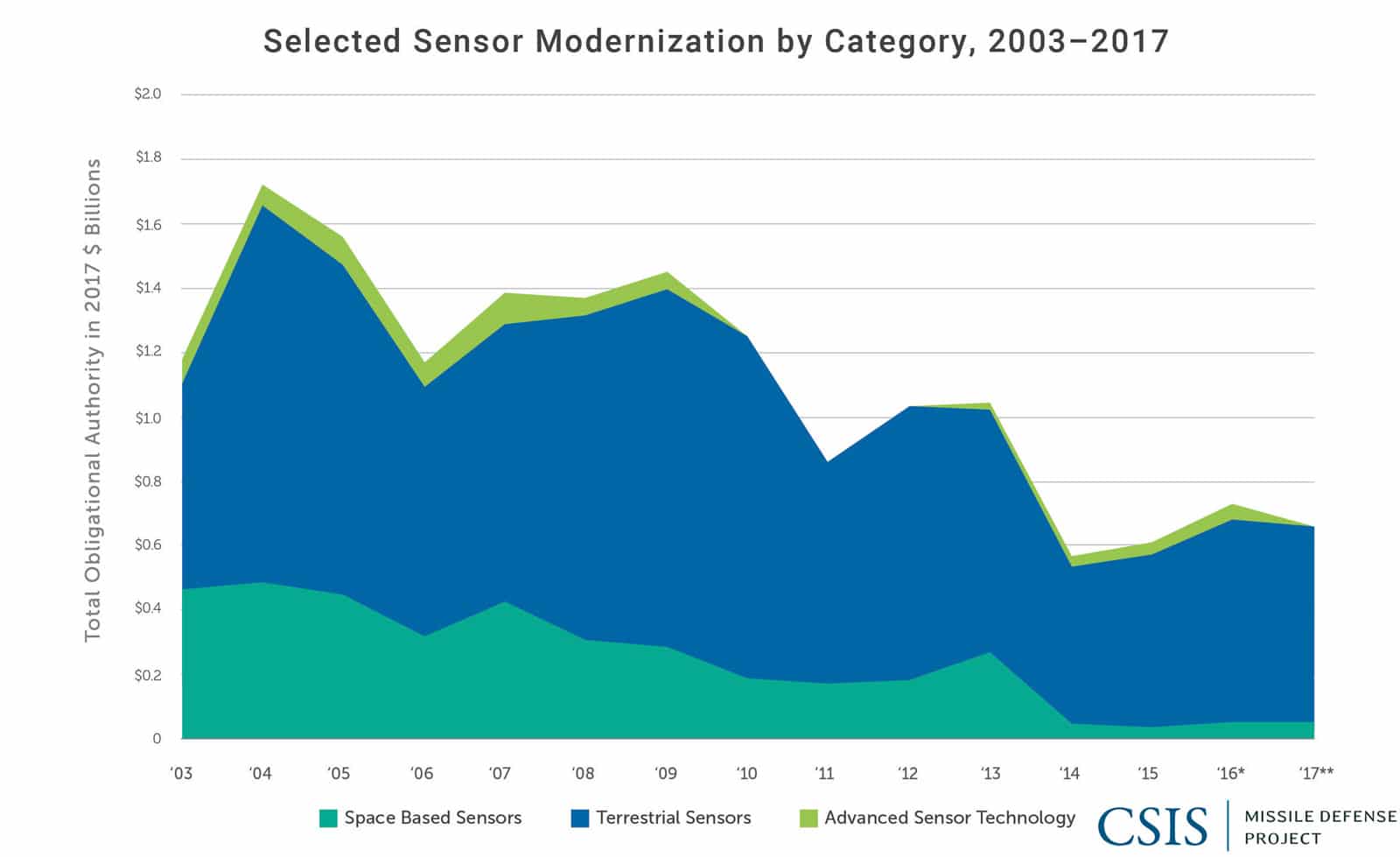
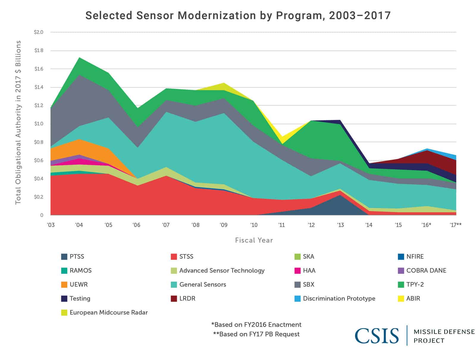
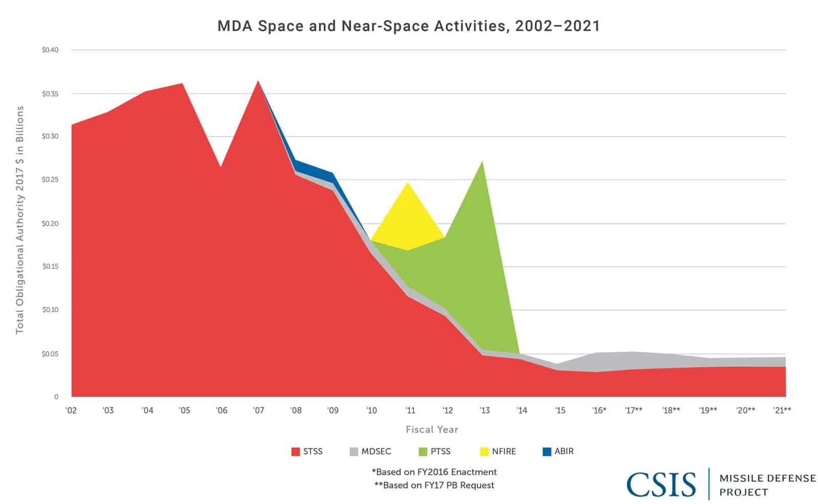
Like other elements of GMD, however, budgets for modernizing and expanding the sensor network have been depressed since 2009 (Figures 5.2. and 5.3).
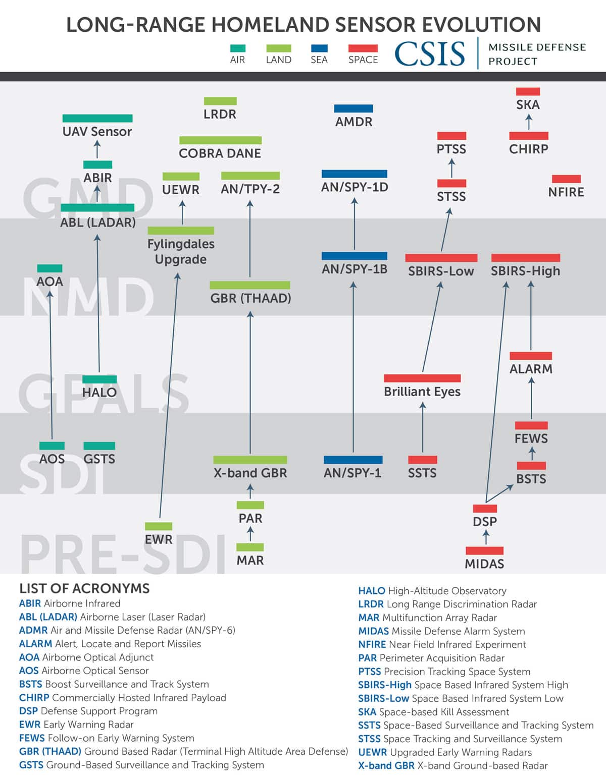
GMD sensor coverage has deepened dramatically since 2004, but significant work still remains, most notably in terms of persistent birth-to-death tracking and improving discrimination. The problem of discrimination has been a focus of considerable effort since, and even before, the 1980s. As long as the United States continues to focus on exoatmospheric intercept for homeland defense, “the hard fact is that no practical missile defense can avoid the need for midcourse discrimination.”2
TERRESTRIAL RADARS
Terrestrial radars operate by emitting directed radio waves into the atmosphere and space. These radio waves reflect off objects. Some of these waves bounce back to the radar station, which it collects and analyzes to determine the object’s location and form an image. Since radar was first employed during World War II to detect formations of German aircraft flying toward Britain, significant advances have been made in the fidelity of imagery available and in the ability to process that information into firing solutions.
Many of the limitations of today’s homeland missile defense sensors used for homeland defense are inherent in radars located on the earth’s surface. The shape of the earth limits the field of view of any terrestrial radar as the earth curves away from the arrays, which requires terrestrial radars to be distributed forward, closer to likely adversary missiles. The inherent trade-offs between radar frequencies and power limitations can restrict a given radar to serving either the tracking or the discrimination mission. These factors increase the number of required radars to produce adequate coverage.
GMD draws data, or phenomenology, from multiple radars around the globe. These include some of the newest sensing systems the United States fields, such as the TPY-2 X-band radar. Others are among the oldest still operating, such as the PAVE PAWS network of Early Warning Radars built during the late 1970s and early 1980s that provide early detection of a Soviet nuclear attack. These have been upgraded to provide missile defense tracking capability. Based on their geographic positions and the frequencies of radio waves they emit, each radar brings certain strengths to the homeland missile defense mission. Each also has weaknesses, for which other sensors must somehow compensate.
Bandwidths
One differentiator of radar capability is the frequency of radio wave it emits. Higher frequencies, such as X-band, provide high fidelity images, the kind useful for discriminating warheads from debris and other objects in a threat cloud. This frequency, however, can limit an X-band radar to scanning a narrow area, making it somewhat less useful for detection and tracking over a wider area. Lower frequencies, such as L-band and Ultra-High Frequency (UHF), lack similar sharpness but are capable of covering much larger areas at lower power output. This makes them suitable for tracking the position of a threat object over great distances. S-band, a sort of “middle” frequency, can provide a balance between discrimination and tracking capability.
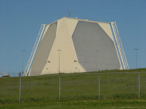
Upgraded Early Warning Radars
Upgraded Early Warning Radars (UEWR) are long-range solid-state phased array radars that operate in the UHF band, which allows them to provide detection, tracking, and classification data to the BMDS, but little ability to discriminate objects.3 Currently, the United States has three UEWRs, located at Beale Air Force Base (AFB) in California, Fylingdales in the United Kingdom, and Thule AFB in Greenland. Upgrades are under way on the Early Warning Radars at Cape Cod, Massachusetts, and Clear, Alaska. UEWRs also perform space situational awareness missions for the Air Force Space Command, which sustains the radars.4
The difference between an Early Warning Radar and an Upgraded Early Warning Radar is mostly software that allows the radars to more effectively track missiles and to then communicate effectively with the broader BMDS. UEWRs have an upgraded receiver exciter and frequency time standard, allowing them to do target classification and missile tracking to cue other sensors and interceptors.5
This does not preclude UEWRs from performing the same missions as the other EWRs, but gives them an advanced capability and the ability to communicate with other missile defense assets.6
Each panel of an Early Warning Radar has a 120-degree azimuth. The sites at Beale AFB and Thule each have two-panel configurations for 240-degree coverage, while the radar at Fylingdales has a three-panel configuration, allowing the system to have full 360-degree tracking capability.7
The first EWR reconfigured for the missile defense mission was that at Beale Air Force Base in California, which completed its upgrade in 2005—after limited defensive operations began in late 2004.8 The Beale UEWR participated in its first GMD test in 2006, proving its capability to track a target and relay information to other GMD components.9
Because of its proximity to the GMD interceptor site at Vandenberg AFB, the Beale UEWR has been used in every GMD test within its operational range, serving as the demonstration platform for the other UEWRs that are farther from testing regions.10 Fylingdales became the site of the second operational UEWR in 2007.11
The Thule AFB UEWR completed its first shift with upgraded software in 2009.12
The near-term improvements to the BMDS sensor network include the EWRs at Cape Cod and Clear. Cape Cod will likely be upgraded in late-2017 and the Clear site will be operational in mid- 2017.13 When they become UEWRs, they will provide additional coverage for missile tracking for both the East and West Coasts.
Cobra Dane
The Cobra Dane Radar Upgrade is an L-band radar with a single face with a 136-degree azimuth located on Shemya Island, Alaska, at Eareckson Air Station. At 95 feet in diameter, the radar face is larger than the UEWRs. Cobra Dane can detect objects out to 2,000 miles to provide missile tracking and classification data sufficiently accurate to commit the launch of interceptors and update target tracks during interceptor flight.14 Information used from this classification is stored and integrated into intercept plans. How a given missile looked and behaved in past launches both helps identify it and show characteristics that would help in its defeat.
Due to the location of the Cobra Dane radar at the far western edge of the Aleutian Islands, MDA has never been able to use it for a GMD intercept test, though it has probably been used to track test flights of Soviet and Russian ballistic missiles.15
Cobra Dane was integrated for ballistic missile defense missions in 2004, and in February 2009 was transferred from MDA to the Air Force for sustainment.16
The major difference between the Cobra Dane and UEWRs is its L-band frequency rather than the UHF band used by UEWRs. This allows Cobra Dane to perform more accurate classification of objects—for instance, Russian ICBMs heading to the Kamchatka test range, 1,200 miles from Shemya. As its deputy program manager explained in 2015, “The radar’s small object detectability performance is better than any of the other Space Surveillance Network phased-array sensors currently available.”17 This historical purpose explains why Cobra Dane also has only one radar panel, limiting its observation azimuth, in contrast with the multipaneled UEWRs.18
In 2013, the United States Air Force proposed to operate Cobra Dane at a quarter power as a means to save $5 million, reducing the radar’s ability to track objects in space. In response to provocations by North Korea, however, the Air Force opted to keep the radar at full power.19
Cobra Dane is part of a larger “Cobra” family of sensors dedicated to missile tracking and classification. The Air Force also operates the Cobra King, a ship-based dual X-band and S-band radar, for missile tracking missions. The radar is much smaller than the Sea-based X-band Radar (SBX) and has a shorter range, but being based on a ship rather than a converted oil drilling rig gives it greater mobility and forward reach. The predecessor to Cobra King, the Cobra Judy, was commissioned in 1985 as a means to track and gather data on the terminal phase of ballistic missile flights.
Cobra King began operations in 2014 and was upgraded to simplify repairs and allow the X-band and S-band radars to function independently.20 The Air Force also operates Cobra Ball, a modified C-135B that can observe ballistic missile flights at long range, and previously operated Cobra Eye, which used a sensor on an RC-135X that tracked reentry vehicles from ICBMs.21
These systems gather useful data that informs U.S. missile defense databases and algorithms, but while their concept of operations points to the utility of airborne and seaborne platforms for missile tracking, these systems are not actively integrated into the BMDS.
TPY-2 X-band Radar
The Army-Navy Transportable Radar Surveillance and Control Model-2 (AN/TPY-2, or TPY-2) radar is a high resolution, phased array X-band radar designed and built specifically for missile defense. The TPY-2 can be deployed in one of two modes: terminal or forward-based. In terminal mode, it is integrated with a Terminal High Altitude Area Defense (THAAD) system, serving as its primary sensor. In forward-based mode, the radar is integrated with the broader BMDS and provides sensor tracks of missiles in boost and early midcourse.
By the end of 2017, the United States will have 12 TPY-2s, seven of which will be in terminal mode assigned to THAAD units.22 The terminal mode TPY-2 supporting the THAAD on the island of Guam contributes to homeland missile defense in the sense of defending U.S. territory.23 Another five are already in forward-based mode (FBM), two of which are deployed to Japan, monitoring North Korean missile activity.24 Those in Japan have been called “redundant,” but are perhaps better understood as complementary, given their dif¬ferent latitudes and orientations.25 The remaining three are deployed in Turkey, Israel, and the Persian Gulf region. By way of comparison, earlier NMD architecture had envisioned nine homeland defense X-band radars to be both colocated with the several UEWRs as well as at a few other sites.26
The 2012 NAS study recommended five ground-based X-band radar sites, but stacking two TPY-2s atop each other at each site to enhance their ranges.27
From forward locations, the TPY-2s are able to detect and track missiles in their boost and early midcourse phases, determining information such as speed and trajectory. The high resolution imagery also allows the radar to identify the type of missile fired. TPY-2s focus their beams narrowly, cannot provide 360-degree coverage, and are further limited by the curvature of the earth. This means that long-range missiles heading toward the United States will eventually fly out of the forward-based TPY-2’s field of view, requiring rearward radars to pick up the track.
Sea-based X-band Radar (SBX)
The SBX is a unique X-band radar based atop a North Sea oil rig platform. The SBX produces very high resolution images of incoming threat clouds. Its high fidelity imagery provides information that helps the kill vehicle discriminate between lethal objects and debris within the threat cloud. The SBX has contributed to 12 tests of the GMD system and provided tracking and kill assessment for Operation Burnt Frost in February 2008, when an Aegis BMD destroyer and an SM-3 interceptor, modified for the mission, shot down a U.S. government satellite falling out of orbit, out of concern that the satellite’s toxic fuel payload might pose a danger to populations. It has also been deployed on numerous occasions to monitor North Korea’s long-range missile tests and routinely participates in flight tests of U.S. intercontinental ballistic missiles. The SBX program was approved by MDA in October 2002, began sea trials in 2005, and has been in service since. The operational SBX is technically designated “SBX-1,” reflecting an initial expectation that one or more platforms would be built, with the second perhaps being located in the Atlantic.28

Initial plans intended the SBX to be permanently stationed at Adak Island, Alaska. MDA constructed a special mooring station for SBX there, completed in 2007. MDA ultimately determined that the cost of maintaining a fixed mooring was greater than keeping SBX mobile, however, and SBX has since been stationed at Pearl Harbor. News reports in late 2016 indicate that the SBX operated for a period of time near the Korean peninsula to monitor North Korean missile launches.29
SBX also has performance limitations. The radar cannot operate as a stand-alone sensor. The cost of its high resolution is its relatively narrow 25-degree viewing arc, which has been compared to looking through a drinking straw. SBX has a limited ability to track an incoming missile but relies on other sensors to provide the target’s location and trajectory. While in some cases it is an asset, SBX’s mobility also presents a drawback: it must sail from port in Hawaii to the western Pacific for optimal positioning. Weighing over 4 million pounds, SBX is quite slow (eight knots per hour), requiring significant warning time to relocate the platform prior to the launch of an enemy missile. Another challenge of SBX is the high operating costs at sea.30
Aegis (SPY-1 Radar)
Another important component of homeland missile defense is the fleet of Aegis BMD ships, each equipped with a SPY-1 S-band radar capable of tracking and providing discrimination data on ballistic missiles. As BMD ships are typically forward-deployed, they are often positioned to observe a hostile missile’s late boost and early midcourse phase, perhaps after the missile passes over a forward-deployed TPY-2 and before it would be acquired by a longer-range sensor. Since October 2002 (IFT-9), Aegis BMD ships have participated in every GMD intercept test. As of late 2016, 34 Aegis BMD ships in the U.S. Navy were equipped to carry out this mission. These include 5 Ticonderoga-class cruisers and 29 Arleigh Burke–class guided missile destroyers. The degree to which Aegis ship-based radars are able to contribute to tracking and discrimination is contingent upon advance warning, their location at the time, and their preoccupation with other missions.
Aegis BMD ships use S-band radars, but they have a more limited range than the SBX or TPY-2s. Supporting homeland missile defense is but one of their many missions, including fleet defense, regional missile defense and offensive operations. These ships are a high demand, low density asset, with geographic, operational, and technical limitations on their availability to support GMD. The limited range of the SPY-1 radars also requires careful placement to contribute to homeland defense.
Upgrades to Aegis Baseline 9C hardware have now become available, allowing the ships to perform both air defense and ballistic missile defense simultaneously. The majority of the Navy’s contingent of Flight IIA Arleigh Burke–class destroyers (not currently BMD capable) are being upgraded to Baseline 9C hardware, which may make them capable of tracking ballistic missile threats to the U.S. homeland, in addition to air and fleet defense.31
The Flight III Arleigh Burke destroyers will feature the SPY-6 radar, also referred to as the Air and Missile Defense Radar (AMDR). The new radars will include an active electrically scanned array (AESA) said to be 30 times more powerful than the current SPY-1 radar. The system will also enable digital beam forming, allowing more precise tracking as well as the potential to itself execute electronic attacks, perhaps serving as a nonkinetic effector.32
The final ship ordered in FY 2016 will be the first Flight III built and the first to deploy the AMDR.33
Long Range Discrimination Radar
The Long Range Discrimination Radar (LRDR) is a large solid-state, two-faced, phased array S-band radar currently under development, expected to become operational by 2020. In January 2016, Vice Admiral James Syring described the LRDR as providing “24/7 long-range discrimination, precision tracking and hit estimate . . . to give the warfighter confidence that the shot doctrine can be reduced with much more up-to-date and much more relevant information for the more complex threats.”34 The choice of S-band for the LRDR will somewhat reduce its discrimination capability relative to X-band but enhance its capability to track incoming missiles over greater distances, with a much larger field of view. Cost control was also likely a motivation for keeping the LRDR at S-band.35
MDA announced in May 2015 its intention to locate the LRDR at Clear Air Force Station in Alaska.36 Another site option was on Shemya Island at the far edge of the Aleutian Islands, also the site of Cobra Dane. Locating LRDR on Shemya would have placed it around 2,400 kilometers closer to North Korea, thus making it more capable of tracking North Korean missiles earlier in their flight.
Indeed, Shemya was the location originally selected for an X-band radar during the Clinton administration to serve this same purpose.37
Costs and other operational difficulties associated with such a remote location were likely factors in the choice of Clear.
The deployment of LRDR may reduce reliance on the SBX in the Pacific, potentially allowing it to move elsewhere, such as the East Coast. Such a relocation would provide additional coverage for missiles coming from Iran.
SPACE-BASED SENSORS
Space-based sensors offer perhaps the best opportunity to detect and track incoming missiles as well as determine the results of an intercept attempt. Space-based sensors offer significant range advantages over their terrestrial counterparts, but in return often must sacrifice detail to get a wider picture. Space-based platforms offer the promise of the “holy grail” of missile tracking, following a missile from launch to reentry or intercept. The United States has, nevertheless, no plans to build or field space-based tracking sensors, and today’s STSS demonstrators are not operationally integrated into the BMDS.
Overhead Persistent Infrared (OPIR)
OPIR is a family of satellite constellations overseen by the U.S. Remote Sensing Systems Directorate located at Los Angeles Air Force Base. Among the four main satellite groups for which the Directorate is responsible, two contribute to homeland missile defense: the Defense Support Program and the Space-based Infrared System.38
Defense Support Program (DSP). DSP consists of a constellation of infrared sensing satellites operated by the U.S. Air Force Space Command. These sensors have been in operation since 1970 and provide launch warning of enemy missiles by detecting the intense heat created by the plume of exhaust of a boosting missile. Incoming information from DSP is gathered and disseminated by the Air Force’s 2nd Space Warning Squadron, a unit within the 460th Space Wing located at Buckley AFB, Colorado.39 The unit has performed this role since 1992. The last DSP launch took place in 2007 (DSP-23). According to media reports, however, DSP-23 unexpectedly stopped working in September 2008.40
The loss underscored the need to accelerate replacement of the aging constellation.
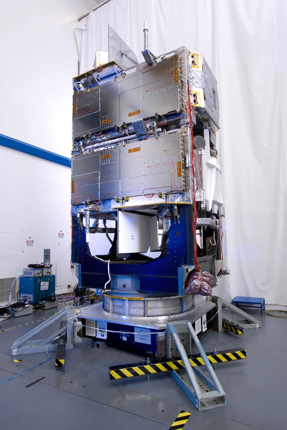
Space-based Infrared System (SBIRS). To replace the DSP satellites, the United States Air Force has begun deploying the SBIRS constellation. These satellites include dual sensor platforms that can both scan over wide territories to detect activity and also stare at areas of interest to detect lower heat signature events like the launch of short-range tactical ballistic missiles. The sensors are independently tasked, meaning the satellite can simultaneously scan a wide territory and stare at a particular area of concern. The first SBIRS satellite, SBIRS GEO-1, was launched in 2011, followed by SBIRS GEO-2 in 2013.41 SBIRS GEO-3 was successfully launched in January 2017.42
In addition to the dedicated satellites, SBIRS also includes missile warning sensors hosted on classified satellites in high elliptical orbit. There are currently two of those sensors in orbit and they were launched in November 2006 and June 2008.43
Missile Defense Agency Satellite Programs
Space Tracking and Surveillance System (STSS). In 2001, MDA took what was originally the low earth orbit part of the SBIRS program (SBIRS-low) and renamed it the Space Tracking and Surveillance System. STSS is designed to provide persistent, “birth-to-death” sensor coverage, in depth, of missiles from space. This vantage point helps discrimination because it allows the sensors to see where decoys deploy or debris is created.
The first two demonstration STSS-D satellites launched in September 2009.44 In March 2011, the STSS-D demonstrated birth-to-death tracking of a test ballistic missile for the first time.45
This tracking and warning significantly expands the defended area by permitting “launch on remote,” the earlier launch of intercept missiles before the threat comes into view of a terrestrial radar. In February 2013, STSS-D provided firing data to an Aegis destroyer for the first time during an intercept test of a medium-range ballistic missile, extending the range of the SM-3.46
Near Field Infrared Experiment (NFIRE). The development of STSS was also informed by an earlier technology project known as the Near Field Infrared Experiment. Launched April 2007, NFIRE was a low-earth orbit satellite designed to collect imagery of boosting missiles and rockets to improve discrimination, as well as aid the development of future space trackers and kill vehicle seekers. NFIRE was initially intended to be equipped with an experimental kinetic kill vehicle, but this element was scrapped prior to launch. In its place went a secondary payload designed to conduct experiments on using lasers for space-to-space and space-to-ground communication. Although only intended for a maximum of two years in orbit, MDA decommissioned NFIRE in August 2015 after eight years in operation.
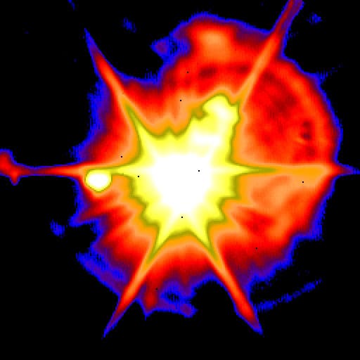
Space-based Kill Assessment (SKA). The Space-based Kill Assessment program is an experimental program pursued by MDA to determine the efficacy of using commercially hosted satellite payloads to place sensors in orbit.47
The sensors will assess intercept success rates and relay information to the warfighter, improving shot doctrine by ensuring that extra interceptors are not launched at a threat that has already been neutralized. This is done by providing sensor data on intercept characteristics, like the energy radiating from the intercept’s so-called fireball, that provide clues about payload type for the target object as well as how the intercept occurred.48
Initial work on the program has been funded by leftover money from the canceled Precision Tracking Space System (PTSS) program. MDA expected to launch the first SKA payload in FY 2016, but due to a reduced budget, the first launch is now scheduled for mid-2017.49
Precision Tracking Space System (PTSS). A proposed follow-on to STSS, the Precision Tracking Space System featured satellites that would have prioritized a larger telescope and relied on subtle movements in space for tracking instead of a complicated gimballed system. This constellation would have grown to between 9 and 12 satellites operating in orbit around the earth’s equator. PTSS was canceled in 2013, shortly after the successful Aegis intercept, based on concerns about the cost of the program.50
A National Academy of Sciences report argued in 2012 that PTSS “does not appear to be justified in view of its estimated life-cycle cost versus its contribution to defense effectiveness.”51
The report concluded that PTSS would only provide marginal improvements in discrimination capability over less costly terrestrial radar alternatives, and that the proposed constellation size was too small to provide effective coverage. Congress seemed to agree, and the program was eliminated.
Gaps in Space Coverage
Unfortunately, a space-based missile tracking solution is still not under way. As MDA Director Syring has observed, “There is no plan today for STSS or PTSS follow on.”52 MDA and the Air Force are nevertheless considering cooperative efforts that could contribute to the missile defense mission. These efforts would focus on putting up multi-mission satellites that could do both missile defense tracking and space situational awareness, for example.53
Such an arrangement could be a way for MDA to defray the large costs of building a large constellation of satellites by sharing them with other Services. At the same time, the history of SBIRS carries a cautionary tale: stacking too many missions onto a single platform can inadvertently drive up cost and slow delivery. An alternative approach would be to take the missile warning payload and modularize it, to be hosted on a wide variety of other satellites.
In the absence of operational space-based sensors overhead, the homeland missile defense mission is dependent on only terrestrial radars for tracking and discrimination. This places a larger burden on the sensor network, which makes it harder to identify the objects within the threat cloud of an incoming missile. As such, more of the objects within the cloud would need to be engaged to ensure the warhead is destroyed. This in turn means firing more interceptors at a single threat cloud, reducing the effective capacity of the GBI magazine.
COMMAND AND CONTROL
The command and control network for GMD operates in the first instance through GMD Fire Control (GFC) and is supported in some ways by the broader Command and Control, Battle Management, and Communications (C2BMC) network for the broader BMDS. Data from various sensors is sent to the GBI launch sites via Defense Satellite Communications System (DSCS) facilities or by redundant ground-based communication lines. To maintain GMD readiness, personnel stationed at Fort Greely and Vandenberg AFB conduct daily missile engagement simulations.
GMD Fire Control (GFC)
Operated at both Schriever AFB in Colorado and Fort Greely in Alaska, the GFC system collects data from the many space- and land-based radars and sensors. GFC receives data from a worldwide network of radars and satellites on incoming missile and aerospace threats via the DSCS sites at Fort Greely and Vandenberg AFB. Information is communicated to the Command Launch Equipment (CLE), and the CLEs then formulate firing solutions.
The operators then use that data to task and support the intercept of targets using GBIs. After an interceptor is launched, the In-Flight Interceptor Communications System (IFICS) Data Terminals (IDTs) communicate this information to the GBIs in flight, either westward through Fort Greely and Vandenberg, or through Fort Drum, New York, for an eastern trajectory.54 Two upgrades are currently planned for GFC.55
In-Flight Interceptor Communications System (IFICS) Data Terminal (IDT)
The IDTs are facilities that relay communication between the GMD Fire Control and the GBIs while in flight. There are currently six IDT facilities: two at Fort Greely, two at Vandenberg, one at Fort Drum, and one at Eareckson Air Station. Construction of the Fort Drum IDT facility was completed in 2015, and it became operational in March 2016. This latter IDT is particularly important for the capability to intercept a future Iranian ICBM because communication to the GBI must be line-of-sight. Additionally, enhancements are currently being made to the IDT systems at large to enable on-demand communications with the kill vehicle (KV).
Command and Control, Battle Management, and Communications (C2BMC)
C2BMC is an operational software and network program. It is the “integrating element” that collects and processes sensor information to provide a complete picture of the missile defense battlespace to Combatant Commanders and other high-ranking defense officials to facilitate decisionmaking.56 Not all sensors use the C2BMC network to transmit data to GFC. The UEWRs, Cobra Dane, and SBX, for example, send their data directly to GFC.
C2BMC first became operational in 2004 and has since gone through nine phases of development, or “spirals.”57 Each spiral has incrementally improved the system’s ability to integrate sensors and interceptors, as well as provide a more complete, uniform, and robust picture of the battlespace. The most current spiral, S6.4, is expected to be replaced by S8.2-1 in the 2017–2018 time frame. This spiral will be fielded to NORTHCOM and PACOM and will allow C2BMC to integrate data from TPY-2 radars, SBX, UEWRs, Cobra Dane, and various space sensors. It will also reportedly give the system five times more tracking capability. Upgrade 8.2-5 will begin supporting LRDR sensor management.58
According to a recent GAO report, the C2BMC program has in recent years been a source of delay for the overall BMDS architecture. C2BMC’s purpose is to integrate various elements of the system, but schedule slips, funding reductions, and changing priorities have required human operators to direct some of the system’s tasks instead of using a more automated option. Related improvements are expected to be deployed in 2020.59
Manning GMD
Dedicated homeland missile defense units fall under the purview of the U.S. Army’s 100th Missile Defense Brigade, which is based out of Schriever Air Force Base in Colorado Springs. The unit is a multicomponent brigade made up of both regular Army Soldiers and Army National Guardsmen.60 The 49th Missile Defense Battalion mans the GBI site at Fort Greely, consists of Alaska National Guardsmen, and reports to the commander of the 100th Missile Defense Brigade.61
The California Army National Guard mans the Vandenberg site as part of Detachment 1, another subcomponent of the 100th Missile Defense Brigade.62
These units, assigned to the U.S. Army Space and Missile Defense Command for force provision, are under the operational control of USNORTHCOM. Although comprised of National Guardsmen, they operate full-time and conduct missile engagement simulations on a daily basis.
At MDA’s creation, its task was to develop and field missile defense systems with the intention of then transitioning them to the Services. PATRIOT, for instance, was returned from MDA to the Army in 2003. Full responsibility for procurement and operating costs for THAAD may eventually transition to the Army, and Aegis/SMs to the Navy. GMD, however, poses a more challenging question as to which Service, if any, should assume responsibility for ongoing operations and budgeting. While the budget for GMD remains in MDA, manning has always been the purview of the Army. The UEWRs and Cobra Dane radars, however, are all operated and sustained by the Air Force.
Footnotes
- Committee on an Assessment of Concepts and Systems for U.S. Boost-Phase Missile Defense in Comparison to Other Alternatives, Division on Engineering and Physical Science, National Research Council, Making Sense of Ballistic Missile Defense: An Assessment of Concepts and Systems for U.S. Boost-Phase Missile Defense in Comparison to Other Alternatives (Washington, DC: National Academies Press, 2012), 152.
- Ibid., 10.
- Missile Defense Agency, “Upgraded Early Warning Radars, AN/FPS-132,” MDA fact sheet, July 23, 2014, https://www.mda.mil/global/documents/pdf/uewr1.pdf.
- Office of the Director, Operational Test and Evaluation (hereafter DOT&E), “2014 Assessment of the Ballistic Missile Defense System,” March 2015, 7.
- John Keller, “Air Force Eyes Upgrades to PAVE PAWS, BMEWS, and PARCS Ballistic Missile Warning Radar,” Military and Aerospace Electronics, February 1, 2012, http://www.militaryaerospace.com/articles/2012/02/air-force-to-upgrade-pave-paws-and-bmews-and-parc-radar-systems.html.
- DOT&E, “2014 Assessment of the Ballistic Missile Defense System,” 7–8.
- Ibid.
- Lieutenant General Henry A. Obering III, Director, Missile Defense Agency, “Missile Defense Program and Fiscal Year 2006 Budget” (statement at hearing before the Senate Appropriations Committee, Subcommittee on Defense, 109th Cong., 1st sess. May 11, 2005).
- “Raytheon’s Upgraded Early Warning Radar Participates in Successful Missile Test,” Microwave Journal, May 11, 2006, http://www.microwavejournal.com/articles/1273-raytheon-s-upgraded-early-warning-radar-participates-in-successful-missile-test.
- DOT&E, “FY 2014 Annual Report,” January 2015, 315.
- “Fylingdales Radar Upgrades Complete,” Nuclear Threat Initiative, August 16, 2007, http://www.nti.org/gsn/article/fylingdales-radar-upgrades-complete/.
- Lisa Meiman, “Thule’s Radar Moves Nation One Step Closer to Possible Missile Defense System,” Air Force Space Command, June 25, 2009.
- James D. Syring, “Hearing on the FY 2017 Missile Defense Agency Budget Request” (unclassified statement before the Senate Appropriations Committee, Defense Subcommittee, April 13, 2016).
- Missile Defense Agency, “Cobra Dane Upgrade,” MDA fact sheet, July 23, 2014, https://www.mda.mil/global/documents/pdf/cobradane.pdf.
- Bart Hendrickx, “Snooping on Radars: A History of Soviet/Russian Global Signals Intelligence Satellites,” Space Chronicle JBIS 58, no. 1 (2005): 11.
- Missile Defense Agency, “Cobra Dane’s Missile Defense Capability Transferred to U.S. Air Force,” MDA news release, February 19, 2009, https://www.mda.mil/global/documents/pdf/09news0002.pdf.
- Justin Oakes, “Cobra Dane Team Moves Forward with Radar’s Sustainment Plan,” Hanscom Air Force Base, July 6, 2015, http://www.hanscom.af.mil/News/Article-Display/Article/846999/cobra-dane-team-moves-forward-with-radars-sustainment-plan.
- DOT&E, “FY 2014 Annual Report,” 313.
- “North Korea Tensions Prompt Change in U.S. Air Force Radar Plans,” Reuters, April 9, 2013, http://www.reuters.com/article/us-korea-usa-airforce-idUSBRE93814N20130409.
- Cobra King was formerly designated the “Cobra Judy Replacement.”
- Dan Taylor, “USAF Missile Defense—From the Sea,” Journal of the Air Force Association: Air Force Magazine 98, no. 1 (January 2015): 48.
- Syring, “Hearing on the FY 2017 Missile Defense Agency Budget Request.”
- Missile Defense Agency, “Fact Sheet: Army Navy / Transportable Radar Surveillance (AN/TPY-2),” July 26, 2016, https://www.mda.mil/global/documents/pdf/an_tpy2.pdf.
- The United States deployed the first TPY-2 to Shariki, Japan in 2007. The second was deployed to Kyogamisaki in December 2014. “Second Missile Defense Radar Deployed to Japan,” DoD news release NR-630-14, December 26, 2014, http://www.defense.gov/News/News-Releases/News-Release-View/Article/605330/second-missile-defense-radar-deployed-to-japan.
- Gary Pennett, “Ballistic Missile Defense PB15 Program Change Overview” (presentation, March 24, 2014).
- James M. Lindsay and Michael E. O’Hanlon, Defending America: The Case for Limited National Missile Defense (Washington, DC: Brookings Institution, 2004), 90.
- Making Sense of Ballistic Missile Defense, 152.
- Ronald Kadish, “Missile Defense Program and Fiscal Year 2005 Budget” (testimony before the Senate Appropriations Committee, Subcommittee on Defense, April 1, 2004), https://www.mda.mil/global/documents/pdf/ps_spring04.pdf.
- Sam LaGrone, “Report: SBX-1 Operated Near North Korea,” USNI News, November 1, 2016, https://news.usni.org/2016/11/01/report-sbx-1-radar-operated-near-north-korea.
- Missile Defense Agency, A Brief History of the Sea-based X-band Radar-1 (Washington, DC: Missile Defense Agency History Office, 2008), 4, https://www.mda.mil/global/documents/pdf/sbx_booklet.pdf.
- There are currently 34 Flight IIA Arleigh Burke–class destroyers not currently configured for BMD. All 34 were initially slated for Baseline 9C upgrades, but this number was cut to 29 in the Navy’s FY 2016 budget. Sam LaGrone, “Navy Again Reduces Scope of Destroyer Modernization, 5 Ships Won’t Receive Any Ballistic Missile Defense Upgrades,” USNI News, March 3, 2015, http://news.usni.org/2015/03/03/navy-again-reduces-scope-of-destroyer-modernization-5-ships-wont-receive-any-ballistic-missile-defense-upgrades.
- Dave Majumdar, “Raytheon Enters New Phase of Next Generation Radar Development,” USNI News, June 24, 2014, https://news.usni.org/2014/07/24/raytheon-enters-new-phase-next-generation-radar-development.
- Sam LaGrone, “Stackley: Arleigh Burke Flight III Destroyer, Air Missile Defense Radar Development on Track,” USNI News, April 7, 2016, https://news.usni.org/2016/04/07/stackley-arleigh-burke-flight-iii-destroyer-air-missile-defense-radar-development-on-track.
- James D. Syring, “Ballistic Missile Defense System Update” (speech, Center for Strategic and International Studies, Washington, DC, January 20, 2016).
- “The Long Range Discrimination Radar at S-band?,” Mostlymissiledefense.com, April 20, 2015, https://mostlymissiledefense.com/2015/04/20/the-long-range-discrimination-radar-at-s-band-april-20-2015/.
- “Department of Defense Identifies Planned Site of Future Long Range Discrimination Radar (LRDR),” DoD news release NR-193-15, May 22, 2015, http://www.defense.gov/News/News-Releases/News-Release-View/Article/605521.
- Lindsay and O’Hanlon, Defending America, 83.
- “Remote Sensing Systems Directorate,” Los Angeles Air Force Base, June 24, 2016, http://www.losangeles.af.mil/About-Us/Fact-Sheets/Article/812306/remote-sensing-systems-directorate.
- “Defense Space Program,” Buckley Air Force Base, August 19, 2015, http://www.buckley.af.mil/About-Us/Fact-Sheets/Display/Article/731843/defense-space-program.
- Andrea Shalal-Esa, “U.S. Missile-warning Satellite Fails,” Reuters, November 24, 2008, http://www.reuters.com/article/us-usa-satellite-idUSTRE4AN8FK20081124.
- “Space-based Infrared System,” Buckley Air Force Base, August 19, 2015, http://www.buckley.af.mil/About-Us/Fact-Sheets/Display/Article/731842/space-based-infrared-system.
- James Drew, “U.S. Air Force Missile Warning Satellites Lifts Off,” Aviation Week, January 21, 2017, http://aviationweek.com/defense/us-air-force-missile-warning-satellite-lifts.
- “Space-based Infrared System.”
- Missile Defense Agency, “Space Tracking and Surveillance System,” MDA fact sheet, July 28, 2016, https://www.mda.mil/global/documents/pdf/stss.pdf.
- Turner Brinton, “STSS Satellites Demonstrate ‘Holy Grail’ of Missile Tracking,” SpaceNews, March 23, 2011, http://spacenews.com/stss-satellites-demonstrate-holy-grail-missile-tracking/.
- Mike Gruss, “Satellites Play Key Role in Successful Anti-Missile Test,” SpaceNews, February 13, 2013, http://spacenews.com/33652satellites-play-key-role-in-successful-anti-missile-test/.
- Mike Gruss, “MDA Kill Assessment Sensors Would Be Commercially Hosted,” SpaceNews, March 20, 2015, http://spacenews.com/mda-kill-assessment-sensors-would-be-commercially-hosted/.
- Robert E. Erlandson et al., “Development of Kill Assessment Technology for Space-based Applications,” Johns Hopkins APL Technical Digest 29, no. 3 (2010): 293.
- Mike Gruss, “U.S. Missile Defense Agency’s Hosted Payload Delayed until Mid-2017,” SpaceNews, April 21, 2016, http://spacenews.com/u-s-missile-defense-agencys-hosted-payload-delayed-until-mid-2017/.
- Amy Butler, “PTSS Kill Leaves Hole in Missile Defense Sensor Plan,” Aviation Week, April 29, 2013, http://aviationweek.com/awin/ptss-kill-leaves-hole-missile-defense-sensor-plan.
- Making Sense of Ballistic Missile Defense, 121.
- James D. Syring, “Department of Defense Briefing by Vice Adm. Syring on the Fiscal Year 2016 Missile Defense Agency Budget Request in the Pentagon Briefing Room” (news briefing, Washington, DC, February 2, 2015).
- Mike Gruss, “MDA Eyes Shared Constellation for Missile Tracking, Space Surveillance,” SpaceNews, July 30, 2015, http://spacenews.com/mda-eyes-shared-constellation-for-missile-tracking-space-surveillance/.
- Syring, “Hearing on the FY 2017 Missile Defense Agency Budget Request,” 11.
- Ibid. “The first, GFC 6B3, provides the Warfighter the capability to operate with 44 GBIs, improves discrimination capability, and adds several Warfighter requested upgrades to improve operational capability. The second, GFC 7A, improves fail-over between redundant systems and system availability by removing the aging Command and Launch Equipment and streamlining the GMD fire control system architecture.”
- “Command and Control, Battle Management, and Communications (C2BMC),” Missile Defense Agency, https://www.mda.mil/system/c2bmc.html.
- DOT&E, “FY 2004 Annual Report,” 327.
- Syring, “Hearing on the FY 2017 Missile Defense Agency Budget Request.”
- U.S. Government Accountability Office, Missile Defense: Ballistic Missile Defense System Testing Delays Affect Delivery of Capabilities, GAO-16-339R (Washington, DC: U.S. Government Accountability Office, 2016), 34–35, http://www.gao.gov/assets/680/676855.pdf.
- “100th Missile Defense Brigade,” U.S. Army SMDC/ARSTRAT, http://www.smdc.army.mil/2008/100thMDB.asp.
- William Yardley, “A Missile Defense System Is Taking Shape in Alaska,” New York Times, December 10, 2006, http://www.nytimes.com/2006/12/10/us/10greely.html?_r=0.
- Steve Bauer, “Vandenberg’s Army Detachment Critical for U.S. Missile Defense,” Vandenberg Air Force Base, January 22, 2010, http://www.vandenberg.af.mil/News/Article-Display/Article/339953/vandenbergs-army-detachment-critical-for-us-missile-defense.